|
|
|
 |
 PCChips M565 |
This is about, how to modify the voltage regulators on an M565, to produce
2.2V.
This was posted on the discussion board of the PCChips Lottery.
I provide this information as is in good faith.
USE THIS INFO AT YOUR OWN RISK!
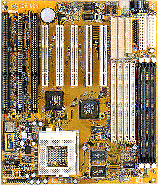
As you know, JP6 selects core voltage. Next to the jumpers are a series of surface mount resistors (R77 through R82). R77 through R81 are associated with jumpers A through E respectively. R82 is not associated with the jumpers, but is wired in parallel to the jumpered resistors. R82 determines the minimum voltage that the board can achieve. (Hopefully, your resistors are numbered the same).
To get below 2.5 volts, R82 must be removed from the circuit. I used a pair of needle-nose pliers and **very carefullY** pinched the resistor in the middle; it's brittle and crumbled to dust- effectively removed it without a soldering iron.
Once modified, I determined how to achieve different voltages by
different combinations of jumpers on A through E of JP6. They are:
A 2.86 ~ 2.9v
B 2.49 ~ 2.5v
C 2.31 ~ 2.3v
AB
3.50 ~ 3.5v
AC 3.44 ~ 3.4v
AD 3.18 ~ 3.2v
BD 2.85 ~
2.9v
BE 2.76 ~ 2.8v
BCE 3.36 ~ 3.3v
CDE 3.00 ~ 3.0v
I initially set jumper on C, but not being satisfied, I wanted to get closer. By my estmitions, placing jumpers on DE should have produced about 2.2, but the regulator circuit dropped core voltage below 1 volt.
I bought a 15 turn 1 Kohm pot at Radio Shack and soldered to the end of an old turbo switch jumper. I jumpered C, which effectively insered the trim pot in series with the surface mount 11.5 kohm resistor of jumper C. I adjusted the pot to about midway, ~500 ohm. I then began to increase resistance until I reached about 2.22 volts. But, the board would hang (volt reg circuit wasn't stable). I kept ajusting resistance back down until I reached 2.26 volts. I've been there for couple of days without any problems.
Hope this is of some value.
James
8674