|
|
|
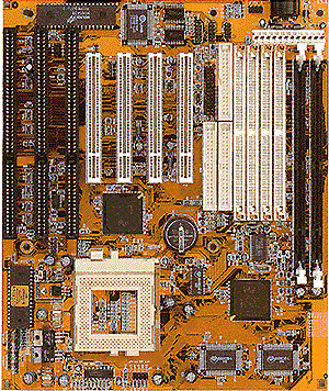
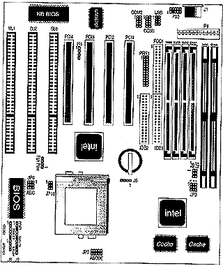
| Pin | Description | Pin | Description |
|---|---|---|---|
| 1 | Power Good | 7 | Ground |
| 2 | + 5V DC | 8 | Ground |
| 3 | + 12V DC | 9 | - 5V DC |
| 4 | - 12V DC | 10 | + 5V DC |
| 5 | Ground | 11 | + 5 V DC |
| 6 | Ground | 12 | + 5V DC |
| Pin | Description |
|---|---|
| 1 | Keyboard Clock |
| 2 | Keyboard Data |
| 3 | N.C. |
| 4 | Ground |
| 5 | + 5VDC |
| J3 | J4 | ||
|---|---|---|---|
| Pin | Description | Pin | Description |
| 1 | +5 VDC | 1 | +5 VDC |
| 2 | Data - | 2 | Data - |
| 3 | Data + | 3 | Data + |
| 4 | Ground | 4 | Ground |
| Pin | Description |
|---|---|
| + | 5V |
| - | Active Low |
| Setting | Description |
|---|---|
| Open | Normal Mode |
| Close | Reset System |
| Internal Battery | 2-3 |
| External Battery | 1-4 |
| CMOS Clear | 3-4 |
| Pin | Description |
|---|---|
| 1 | LED Output |
| 2 | N.C. |
| 3 | Ground |
| 4 | Keylock | 5 | Ground |
| Pin | Description |
|---|---|
| 1 | DATA Out |
| 2 | N.C. |
| 3 | Ground |
| 4 | + 5V |
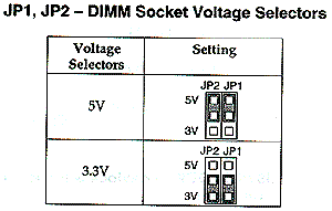 |
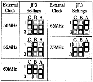 |
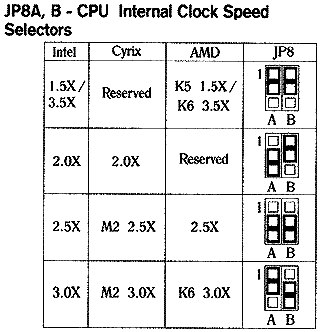 |
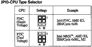 |
| Pin | Description |
|---|---|
| 1 | Mouse CLK |
| 2 | Ground |
| 3 | N.C. |
| 4 | Mouse Data |
| 5 | N.C. |
| 6 | N.C. |
| 7 | N.C. |
| 8 | +5VDC |
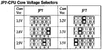 |
| Pin | Description |
|---|---|
| + | +5V |
| - | Active Low |
| Pin | Description |
|---|---|
| Open | Normal Mode |
| Close | Suspend Mode |
| Pin | Description |
|---|---|
| 1 | +12V |
| 2 | Ground |
| 3 | Ground |
| 4 | +5V |